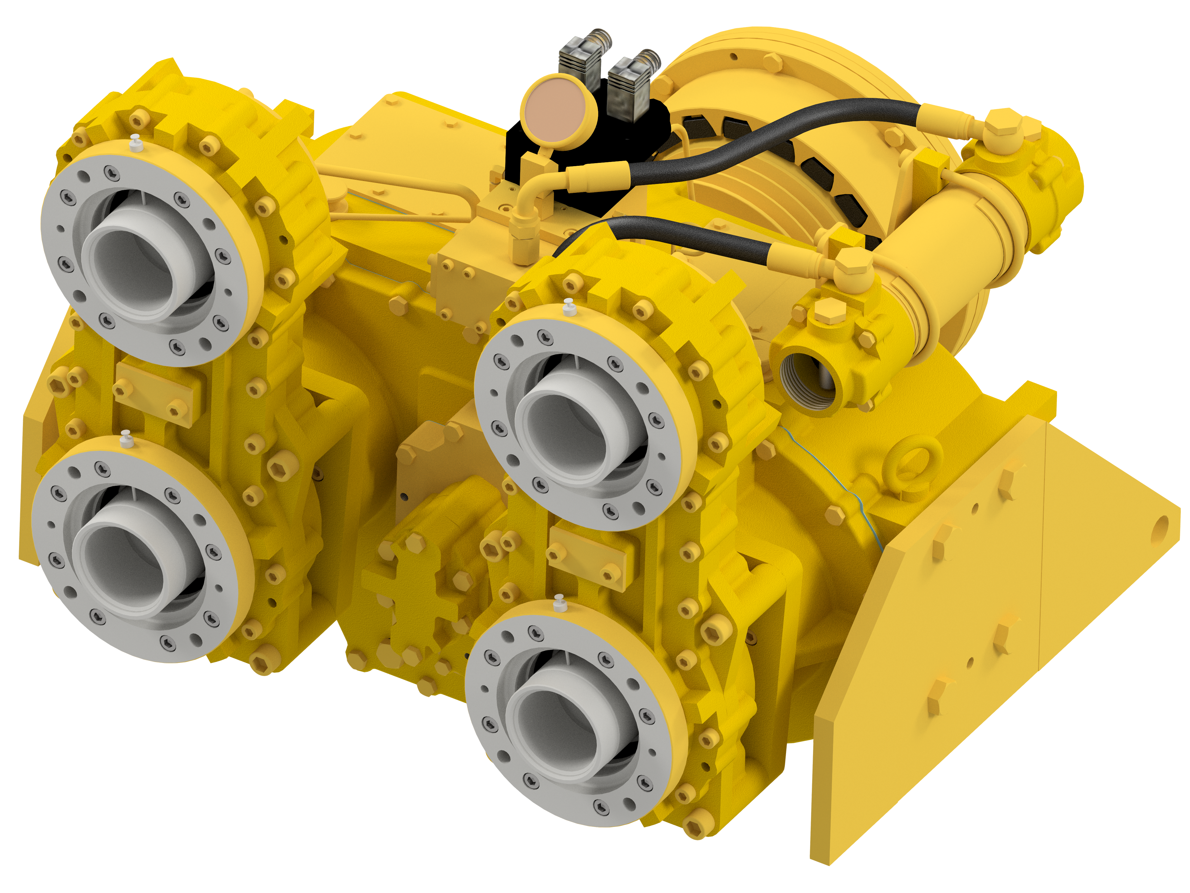
Key features
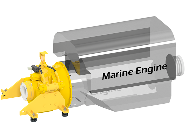
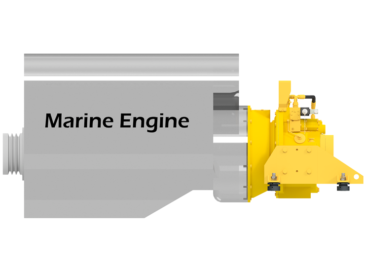
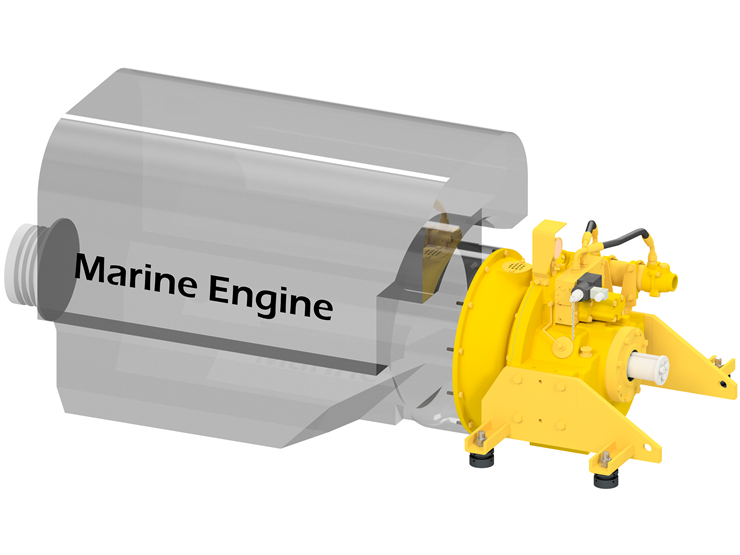
– Attachable for both side of front(pulley) and rear(bell housing) of the engine
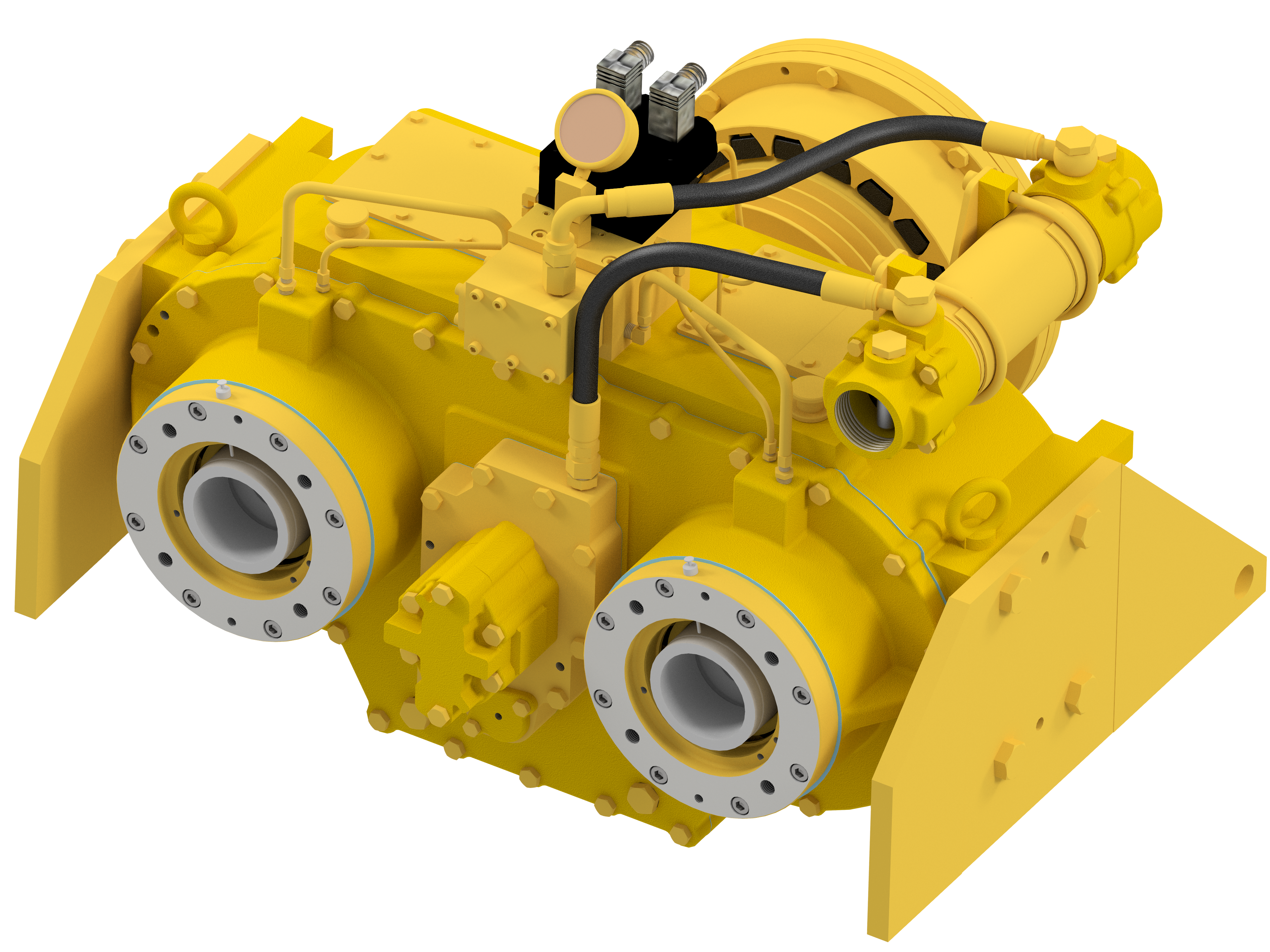
– Independent control by 2 clutches
– Live pulley provided(7″, B type, 2 grooves)
– Perfect brake system to prevent dragging
– Zinc anode on oil cooler prevent the corrosion
– Monitoring function to see rotation of pump shaft
– Pressure gauge provided as standard
– Easy removal metal in oil with Magnet plug
– Compatible Pump Pad to various pumps (If required, machining is needed)
– Extendable 2 output ports each with gear box installation(Option)
Install for
– Drive for hydraulic pump(Side thruster, work craft, crane, etc)
– Pulley (Hydraulic winch, Generator, Air compressor, Sea water pump, etc)
– Anywhere you need to use devices for power train
Options
– Control box
– Pump Mounting Kit
– Bell Housing (SAE#1, 2)
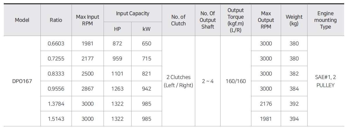
Capacity Table
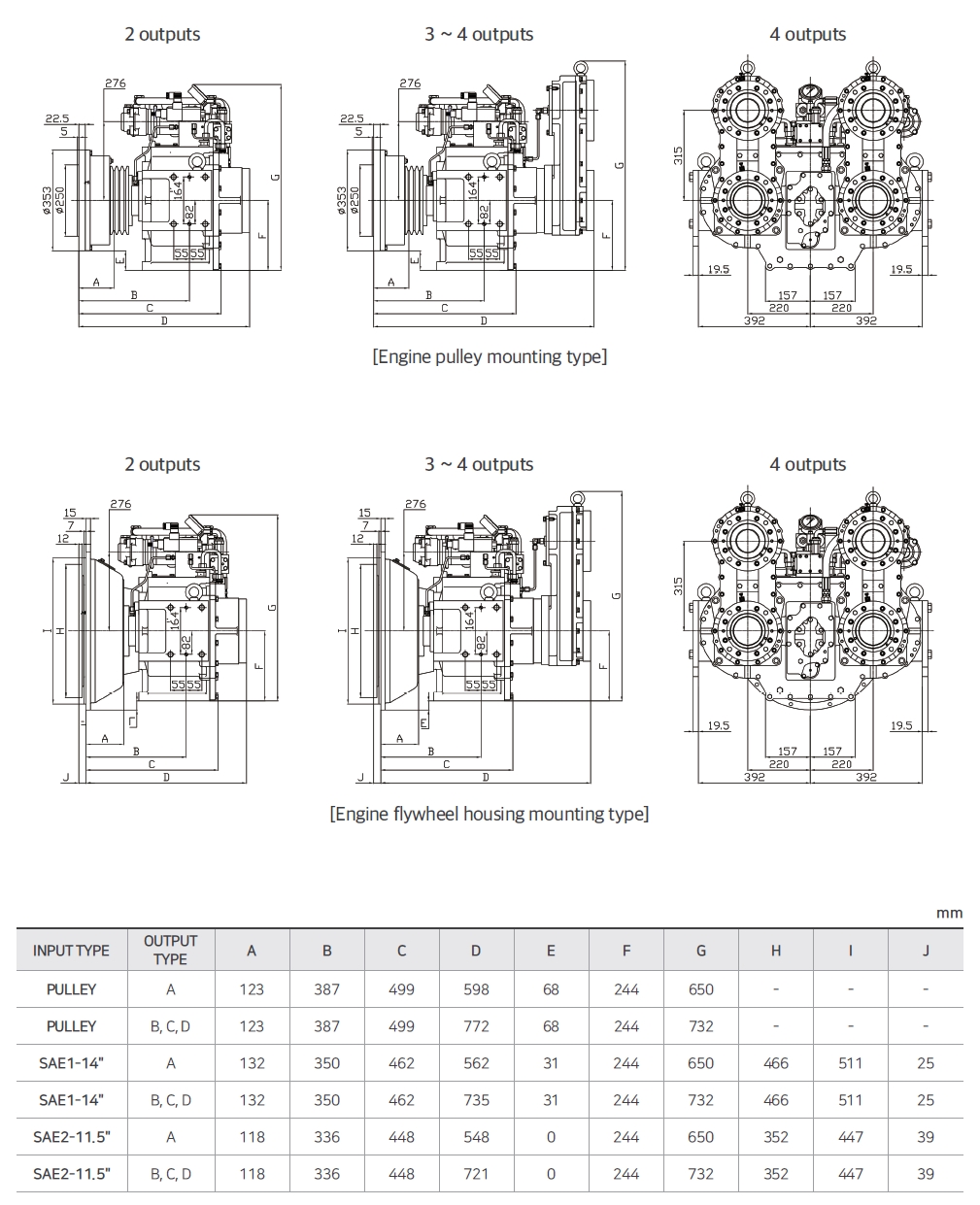
Dimension
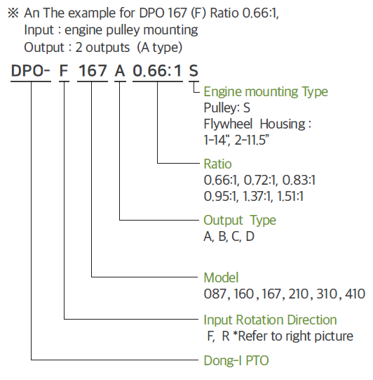
Order Code Configuration
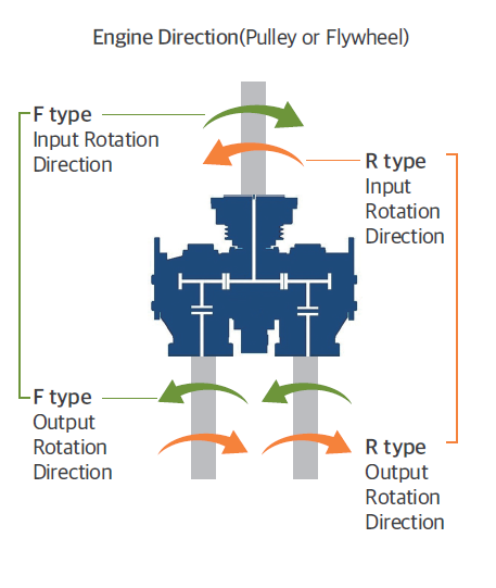
Rotation Direction Type
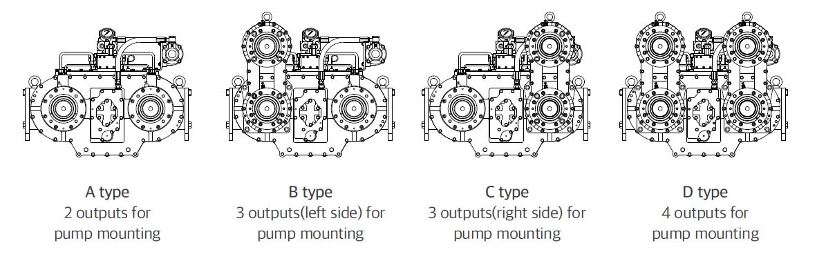
Output Types
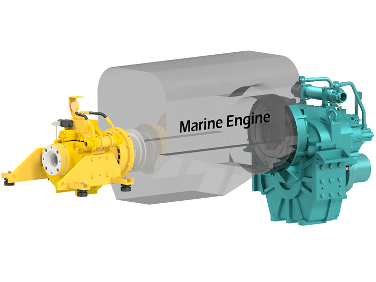
Mounting Example _ Main engine pulley mounting type
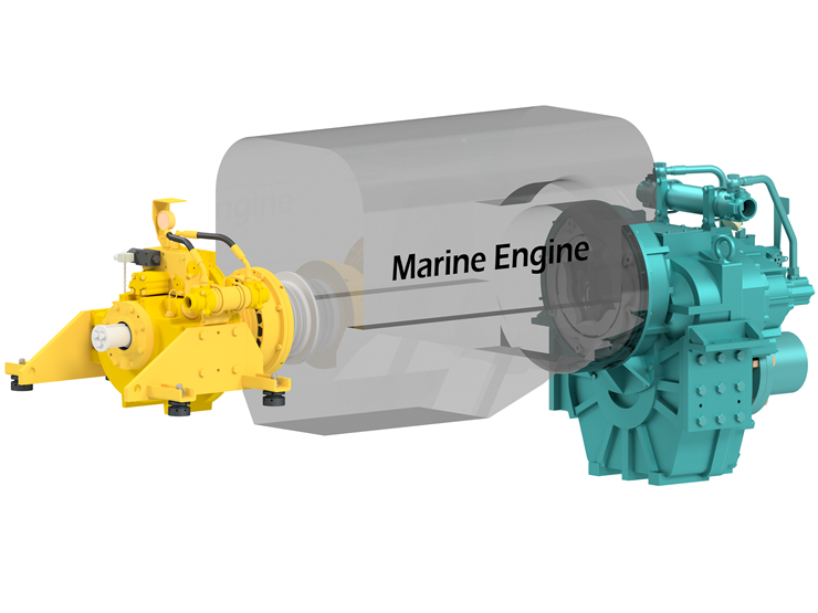
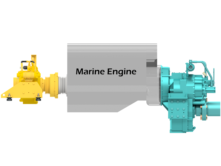
Mounting Example _ Auxiliary engine flywheel mounting type